Strengthen Network Segmentation With Meraki Port Isolation

Sometimes you need ports that reach only the internet and nothing else on the local switch. Meraki port isolation gives you exactly that—keep upstream access open while shutting down Layer-2 device-to-device traffic. Turn it on for the access ports you choose, and those clients can hit DHCP, DNS, and the gateway, but they can’t talk to their neighbors. It’s a quick way to cut lateral movement on guest, lab, and IoT drops without readdressing or writing a pile of ACLs.
From here, we’ll keep it tight: how isolation behaves on the wire, the one setting that bites teams (don’t isolate the uplink), a two-minute check to prove it’s working, and the patterns you can standardize across switches and sites—including multi-switch paths and LAGs. The goal is simple: predictable segmentation that you can roll out fast, providing support without babysitting.
Understanding Port Isolation Meraki Functionality
Port isolation enforces Layer 2 separation between endpoints connected to isolated access ports on the same switch. Endpoints still reach upstream gateways, DHCP, DNS, and cloud apps; they just can’t ARP or switch frames directly to each other. That’s the core value: you contain blast radius on the local switch while preserving normal upstream access.
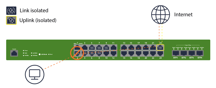
Isolation is port-scoped. You choose which downlink ports are isolated and which are not. Your uplink (or any trunk carrying uplink VLANs) must remain non-isolated so traffic can exit the local collision domain.
Isolation, Traffic Flow, And Port Behavior
Isolated ports cannot forward Layer 2 frames to other isolated ports on the same switch. They can forward to:
The switch’s non-isolated uplink/trunk toward the rest of the network
Upstream default gateway, DHCP/DNS servers, and internet services
Switch management/control plane for monitoring and configuration
This provides tight east-west suppression with normal north-south access intact. Think hotel rooms, exam workstations, guest Wi-Fi bridges, or IoT cameras that must never see each other at L2.
VLAN And Trunk Port Interactions
Isolation doesn’t replace VLANs; it augments them. Typical pattern: keep devices in a single VLAN for simple addressing and DHCP, then enable isolation on their access ports to block peer traffic. Trunk ports that carry VLANs upstream stay non-isolated, so routed connectivity works as expected. If you prefer separate VLANs per group, isolation still helps suppress chatter within each VLAN segment.
Management Plane And Monitoring Visibility
Isolation affects data plane peer traffic, not your ability to manage or monitor the switch. Dashboard visibility, port stats, event logs, and link health remain available. Use those to validate behavior and spot mis-tagging or unexpected broadcasts after you enable isolation.
Isolation Vs ACL And Policy Enforcement
Access control lists (ACLs) and Group Policies operate at Layer 3/4 and above. Port isolation tackles the Layer 2 problem—ARP spoofing, broadcast storms, device-to-device pivots—with a single setting per port. In practice, most teams use both: isolation to stop L2 lateral movement; ACLs/Policies to enforce inter-VLAN or upstream security.
Configuring In The Dashboard
You’ll set isolation on each port in the Meraki Dashboard. You can do this ad-hoc while staging, or at scale via templates/API later.
Navigate: Switch → Configure → Switch ports.
Select ports: Pick the access ports you want to isolate (e.g., guest jacks, lab machines, IoT drops).
Enable isolation: Toggle Port isolation = Enabled for those ports.
Confirm VLAN tagging: Verify access VLAN and any voice VLAN settings; isolation doesn’t change VLAN tagging.
Validate uplink behavior: Ensure the uplink/trunk is not isolated. Do not isolate any port that forwards toward your distribution/core.
Save, then test: Renew DHCP on a test device and confirm upstream reachability and blocked peer traffic.
Rule of thumb: Never isolate the uplink.
Applying Segmentation Profiles Across Networks
Most SMB teams manage multiple sites. Consistent isolation matters across those switches so behavior is predictable everywhere.
Template-Based Profile Configuration
Network templates let you define port profiles once, then apply across stacks of switches. Create a profile for “Guest Access (isolated)” or “IoT (isolated),” set VLAN/PoE/voice options, and enable isolation on that profile. Bind your networks to the template so newly claimed switches inherit the same isolation posture.
Automated Deployment via Meraki API
If you already drive switch configs with scripts, the Meraki Dashboard API can set port isolation flags at scale. Typical flow: fetch switch port lists, map them to your naming plan (e.g., “AP-” or “CAM-”), then PATCH those ports to enable isolation. This keeps human error down and makes audits repeatable.
Policy Replication and Multi-Site Sync
Whether you use templates or API, keep a single source of truth for which roles get isolation. That could be a template library or a simple YAML/CSV that your script reads. The goal: same role, same behavior, any site.
Maintaining Traffic Segregation in Inter-Switch Communication
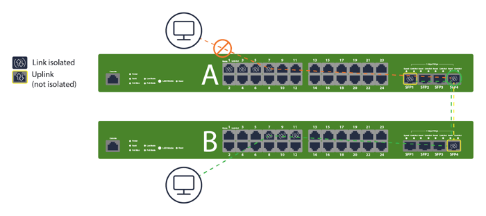
If isolated clients might appear on different access switches (e.g., same VLAN extended across a stack or floor), ensure that inter-switch links remain non-isolated and that your upstream isolation strategy still achieves “no peer-to-peer” semantics. The page 3 visuals show isolation behavior spanning multiple switches while uplinks stay open for north-south flows.
Key Implementation Scenarios and Best Practices
You’ll encounter a few patterns over and over. Build these into your standards so you don’t reinvent the wheel each rollout.
Ensuring Uplink Ports Remain Un-isolated
Start every port plan with: tag the uplink(s) and mark them non-isolated. Label them in Dashboard and on the faceplate. If you later convert a user port into an uplink, remove isolation first.
Checklist:
Identify and label uplinks/trunks on every switch
Confirm isolation = Disabled on uplinks before site cutover
Test: clients on isolated ports can ping gateway/DNS, but not each other
Extending Isolation Across Inter-Switch Communication
When VLANs span multiple access switches, isolation still blocks peer L2 communication per switch. Keep the access ports isolated and carry the VLANs upstream via non-isolated trunks. The “A/B switch” examples visualize this exact design—clients on A and B can reach upstream, but not each other at L2. If you need inter-device communication, don’t use isolation for those specific ports, or move them to a separate non-isolated role.

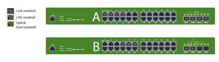
Using Port Isolation with Link Aggregation Groups (LAGs)
Link Aggregation Groups (port-channels) used for switch-to-switch or switch-to-uplink connectivity should remain non-isolated. Use isolation on edge access ports, not on aggregated uplinks. The graphic reinforces this by showing LAGs on uplinks that are not isolated, preserving routed reachability.
Troubleshoot Port Isolation Meraki Deployments
Most “it stopped talking” tickets come down to a few missteps. Work this sequence and you’ll solve issues quickly.
Common Configuration Conflicts
Start with the basics: Is the correct port isolated? Did someone enable isolation on a trunk or uplink? Did a template override a local change? Use the port details page to confirm effective settings, then check recent change logs to see if a bulk action flipped more ports than intended.
VLAN Mismatch and Isolation Loop Scenarios
If isolated clients can’t reach DHCP/DNS/gateway, look for VLAN tag mismatches on the uplink/trunk (native VLAN off by one, missing allowed VLANs, etc.). Isolation multiplies the pain of mis-tagging because endpoints can’t fall back to peer services. Fix the trunk first; do not try to “solve” it by removing isolation.
Monitoring via Event Logs and Port Statistics
Use Dashboard Event log and Port statistics to verify that clients are renewing DHCP and resolving DNS after you enable isolation. Packet counters with no successful ARP to peers are normal on isolated ports; successful ARP to the gateway and steady unicast to the uplink are your green lights.
Testing and Rollback Verification Procedures
Before production cutover, stage a quick table-top:
Plug two test clients into isolated access ports in the same VLAN
Confirm each gets DHCP and can browse the internet
Confirm they cannot ping each other by IP or resolve each other by L2
Move one client to a non-isolated port to validate baseline behavior
Document the results and snapshot port configs for rollback if needed
Compare Port Isolation, Meraki, And VLAN Segmentation
You don’t have to choose isolation or VLANs. You’ll often run both—VLANs for broadcast domains and IP policy, isolation for same-VLAN peer blocking. Here’s how they play together in practice.
Configuration simplicity and flexibility: Isolation is a single-port toggle. VLANs require addressing, DHCP scopes, and routing. Use isolation to keep a simple addressing plan while preventing device-to-device traffic.
Broadcast and traffic control: VLANs limit broadcast domains. Isolation suppresses L2 peer forwarding inside a VLAN. Combining them reduces noise and risk without over-segmenting IP space.
Hybrid VLAN and isolation designs: Common pattern: one “Guest” VLAN, all guest access ports isolated. For IoT, you might carve a couple of VLANs by device type, then isolate access ports to block cross-talk within each group.
Administrative and troubleshooting workload: Isolation reduces the number of ACLs or micro-segments you’d otherwise manage. Keep documentation tight and use templates/API so your ops team doesn’t guess which ports should be isolated at each site.
Hummingbird Networks Drives Secure Meraki Deployment
If you want this to be consistent across every site, Hummingbird can help. We design and deploy Meraki switch configurations for customers nationwide—defining clear port roles, setting up templates or API automation, and validating isolation behavior end-to-end so your team rolls out changes with confidence.
You’ll get fast quoting, real engineers who know Meraki inside and out, and a buying experience built to save you time. Prefer to stay hands-on? We’ll deliver the standards, checklists, and validation steps so your team can handle execution in-house.
Secure your network today and work with Hummingbird Networks to configure your Meraki switches for stronger segmentation and immediate threat protection.
FAQs
What exactly does Meraki port isolation block?
It blocks L2 peer-to-peer switching between isolated ports on the same switch. Clients on those ports can still reach upstream resources (gateway, DHCP/DNS, internet) via the non-isolated uplink.
Should I isolate my uplink or inter-switch trunks?
No. Keep uplinks and inter-switch trunks non-isolated. Isolation belongs on edge access ports
Does isolation replace VLANs or ACLs?
No. Use VLANs to carve broadcast domains and route policy. Use isolation to stop L2 lateral movement within a VLAN. ACLs/Group Policies still handle L3/L4 control between VLANs or to specific services.
How does isolation work across multiple switches?
Isolation is enforced per switch on the isolated access ports. Carry the VLAN upstream over non-isolated trunks; isolated devices on different switches won’t talk at L2 and still reach routed services. The “Switch A/B” visuals on page 3 illustrate this.
Can I use isolation with Link Aggregation (LAG)?
Yes—but don’t isolate the LAG. Keep LAGs non-isolated for switch-to-switch or switch-to-core uplinks. Apply isolation to the edge ports where clients connect.
What’s the quickest way to roll isolation to many sites?
Use Network templates to define port roles with isolation enabled, then bind networks, or use the Meraki API to set isolation flags programmatically. Both approaches keep behavior consistent and reduce human error.
How do I verify it’s working?
After enabling isolation, put two test devices on isolated ports in the same VLAN. They should each get DHCP and reach the internet, but fail to ping each other. Check port stats and event logs in Dashboard to confirm normal upstream traffic and no peer L2 success.
When should I skip isolation?
Skip it when devices on the same switch must communicate at Layer 2 (e.g., clustered appliances or certain VoIP sidecars). In those cases, either use non-isolated ports or move the devices to a role/VLAN designed for intra-device communication.